

For underground infrastructure projects, understanding the practical depth limits of horizontal directional drilling is an important part of planning a safe and achievable bore. Daley Directional Drilling provides horizontal directional drilling in Sydney, where factors such as ground conditions, equipment capacity, bore design and site constraints can all influence how deep a crossing can be installed. Rather than having one fixed maximum depth, HDD capability depends on a combination of technical, environmental and project-specific conditions.
This article explores the factors that determine achievable HDD depth, including geology, rig capacity, drill string and tooling selection, drilling fluid management, entry and exit angles and tracking requirements. It also explains how bore design, project risk, cost and safety considerations help establish practical depth limits, providing a clearer understanding of how deeper HDD installations are planned and managed in real-world conditions.
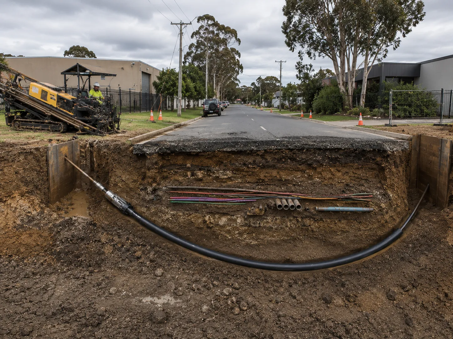
Civil utility HDD installations can range from relatively shallow service crossings to much deeper bores beneath major roads, rail corridors, waterways and congested infrastructure. The appropriate depth is influenced by the utility being installed, asset-owner requirements, existing underground services, ground conditions and surface constraints.
Although HDD equipment can be capable of operating at substantial depths, most civil projects aim to use the shallowest practical alignment that provides the required cover, clearance and protection. Avoiding unnecessary depth can reduce drilling risk, simplify tracking and fluid management and help control construction costs.
Many urban HDD projects for smaller civil utilities are completed at relatively shallow depths. Depending on the project and the requirements of the relevant asset owner, these may include:
Required cover varies considerably between asset owners, authorities, utility types and site conditions. Greater cover may be required beneath roads, areas exposed to heavy vehicle loading or locations where future excavation, grading or erosion is a concern.
Even on relatively shallow projects, the drill path needs to be carefully designed around existing buried infrastructure such as gas, sewer, stormwater, power and telecommunications assets. The need to maintain suitable separation from these services can result in a bore being designed deeper than the minimum cover requirement alone would suggest.
Intermediate-depth HDD is commonly considered where a bore needs to pass beneath multiple existing services or significant surface infrastructure. Applications may include:
Greater depth can provide additional separation from utilities already occupying the shallow subsurface zone and help the bore pass beneath obstacles without disturbing the surface.
At these depths, drilling fluid pressures, bore stability, pipe curvature and tracking requirements generally require closer consideration than for a straightforward shallow installation. The final alignment should therefore be based on project-specific engineering requirements rather than a predetermined depth range.
Deeper HDD alignments are generally reserved for complex crossings where shallower options cannot provide adequate clearance or protection. Examples can include:
At greater depths, the design can be influenced by:
While specialist HDD equipment can support demanding alignments, civil projects generally avoid unnecessary depth because complexity, cost and construction risk can increase as the bore becomes deeper and longer. The preferred alignment is usually the one that safely clears all constraints while remaining practical to construct.
Required HDD depth is influenced as much by what is already in the ground as by the capabilities of the drilling equipment. Adequate cover above the installed pipe and suitable separation from utilities, foundations and structures are important for protecting existing assets and maintaining the long-term integrity of the installation.
Cover and clearance requirements vary by jurisdiction, asset owner, utility type and project. For this reason, indicative figures should not be treated as universal requirements. The design needs to be checked against the relevant specifications and approvals for each crossing.
Minimum cover refers to the vertical distance between the finished surface level and the crown of the installed pipe or conduit.
The required cover can depend on factors such as:
Crossings beneath major infrastructure often require greater cover than installations through open or lightly trafficked areas. HDD designs may also include additional depth beyond the specified minimum to account for drilling tolerances, variations in ground conditions and conflicts with existing services.
Soil and rock conditions can influence the amount of cover considered appropriate. In less stable ground, additional cover may help reduce the risk of the bore reaching the surface or affecting surrounding material. Competent formations can provide greater bore stability, although geological conditions are only one part of determining an appropriate alignment.
Clearance is the separation between a proposed HDD alignment and an existing underground asset or structure.
The minimum acceptable separation varies according to the asset owner, infrastructure type, site conditions and consequences of accidental contact. High-risk infrastructure such as gas transmission pipelines, major water mains, high-voltage electrical assets and rail signalling infrastructure may require particularly conservative separation distances.
Where the shallow subsurface is congested, it can sometimes be more practical to design the HDD alignment beneath an entire group of utilities rather than attempting to steer between individual assets. Identifying and verifying existing underground services is therefore an important part of planning the bore before drilling begins.
Foundations and structural elements also require careful consideration. Bore paths should be designed so that drilling does not compromise building footings, bridge piles, retaining structures or other foundations. Appropriate stand-off distances should be determined using structural and geotechnical information rather than applying a single clearance value to every project.
Managing cover and clearance effectively depends on accurate information about existing underground infrastructure.
Project planning may involve:
Asset owners or authorities may also require design submissions showing the proposed bore profile, minimum cover and separation at critical crossing points.
Requirements can vary significantly for watercourse crossings, roads, rail infrastructure and environmentally sensitive areas. These requirements should be established during planning so the bore can be designed around regulatory and asset-owner constraints from the beginning.
Ground conditions are one of the main factors determining how deep an HDD bore can safely and economically be installed. The same rig and tooling can perform very differently depending on whether the alignment passes through competent rock, stiff clay, loose sand, gravel, cobbles or mixed formations.
Understanding how the ground responds to drilling forces, fluid pressure and bore construction is therefore essential when determining a practical depth.
Competent rock formations can provide favourable bore stability because the surrounding material is generally less prone to collapsing into the drilled hole. With suitable drilling equipment and rock tooling, these conditions can support deeper and more technically demanding HDD alignments.
However, rock drilling also introduces its own challenges, including tooling wear, slower penetration rates, steering difficulty and potentially higher torque requirements.
Greater geological stability does not automatically mean that a very deep bore will be economical or appropriate.
Loose sands, silts, gravels and soft or unstable soils can make deeper drilling more difficult. Depending on the formation, potential problems can include:
These risks can sometimes be managed through appropriate drilling fluid design, bore geometry, tooling selection or temporary casing, but they may also establish a practical limit on how deep an alignment should be.
Groundwater conditions can have a major influence on HDD feasibility. As depth and alignment complexity increase, managing the pressure relationship between the drilling fluid and surrounding formation becomes increasingly important.
If drilling fluid pressure becomes excessive for the surrounding ground, the formation may fracture and drilling fluid can migrate away from the intended bore. Conversely, insufficient support can contribute to bore instability.
Highly permeable sands and gravels can also allow drilling fluid to escape into surrounding formations, making it more difficult to maintain circulation and bore stability.
Lower-permeability soils present different challenges and require drilling fluid properties to be matched to the specific formation.
For deeper projects, drilling fluid management should therefore be considered as part of the bore design rather than treated simply as an operational issue once drilling begins.
Many HDD projects encounter several different ground types along a single alignment.
A bore may begin in clay before passing through sand, cobbles, weathered material and rock. Changes in hardness, permeability and stability can affect steering performance, drilling fluid behaviour and the loads placed on the drill string and product pipe.
The most difficult layer along the route may ultimately determine whether the proposed depth is practical. A narrow zone of unstable soil or fractured rock can be enough to require a change in alignment even when the surrounding formations are favourable.
Geotechnical investigation is therefore particularly valuable for longer, deeper or higher-risk HDD projects. Boreholes, geological records and laboratory testing can help identify problem formations before construction and allow the bore profile and drilling method to be adjusted accordingly.
HDD depth cannot be considered in isolation. It is closely connected to the total bore length, the angle at which the drill enters and exits the ground and the allowable curvature of the drill string and product pipe.
These factors work together to establish the geometry of the crossing and determine how quickly the bore can descend to its target depth and return to the surface.
A longer crossing can provide more horizontal distance for the bore to descend and rise using gradual curves. This can make it possible to achieve greater depth while maintaining suitable bend radii.
However, longer bores also introduce additional challenges. As the alignment becomes longer and more complex, factors such as drill-string loads, pullback forces, drilling fluid circulation and the risk of the product pipe becoming stuck need to be considered more carefully.
Increasing bore length simply to achieve greater depth is therefore not always beneficial. The design needs to balance required cover against the increased construction demands created by a longer alignment.
The entry angle determines how the drill initially travels into the ground.
A steeper angle can help the drill reach depth over a shorter horizontal distance, which may be useful where space is limited. However, overly steep entry or exit angles can create tighter curves and may conflict with the allowable bend radius of the drill string or product pipe.
Flatter entry angles spread the vertical transition across a greater horizontal distance. This can create gentler curvature but requires more space between the rig and the obstacle being crossed.
The appropriate angle therefore depends on available workspace, target depth, product-pipe characteristics and the overall geometry of the crossing.
Allowable bend radius is one of the key constraints affecting HDD depth.
Every product pipe has limits on how sharply it can be curved without introducing unacceptable stress. These limits depend on factors including:
The bore profile is designed using curves that remain within the allowable limits for the drill string and product pipe.
If a proposed alignment attempts to descend too deeply over a short distance, the required curvature may become too tight. The design may then need to be adjusted by lengthening the bore, changing entry or exit geometry or reducing the target depth.
For this reason, maximum practical depth is often governed by bore geometry rather than by the drilling rig alone.
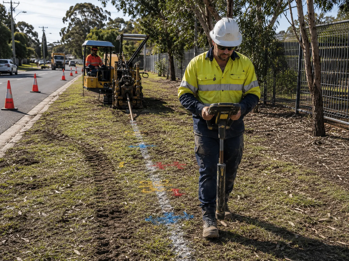
Accurate tracking of bore depth and alignment is essential for keeping an HDD installation within its designed profile.
The appropriate guidance method depends on factors such as bore length, depth, ground conditions, electromagnetic interference, surrounding infrastructure and the accuracy required for the project.
Walkover locating systems are commonly used for utility HDD projects where the drill head can be tracked effectively from the surface.
A transmitter or sonde positioned near the drill head sends information to a surface receiver. Depending on the equipment being used, the locating system can provide information such as:
The locator operator takes readings along the bore path and compares them with the planned alignment so steering adjustments can be made when required.
The practical depth capability of a walkover system varies according to the transmitter, receiver, surrounding ground and electromagnetic interference. Signal reliability generally becomes more challenging as depth increases or when drilling close to electrical infrastructure, steel structures or other sources of interference.
For projects where surface locating is unsuitable, more advanced guidance methods may be required.
Wireline guidance systems can be used for long, deep or critical HDD crossings where conventional surface locating is not suitable.
Downhole sensors can measure information such as:
This information is transmitted to the drilling team and used to calculate the position and direction of the drill head relative to the planned bore profile.
Wireline guidance can be particularly useful for long crossings beneath rivers, transport corridors or other areas where the drill cannot be continuously tracked by an operator walking directly above the bore.
Magnetic interference can affect guidance systems that depend on magnetic measurements. In environments containing pipelines, steel structures, bridges or other potential sources of interference, gyroscopic guidance may be considered.
Gyroscopic systems can provide directional information without relying on the surrounding magnetic field, helping maintain alignment in situations where conventional magnetic guidance may be unreliable.
Depth and alignment information can also be recorded throughout the drilling process to produce an as-built record of the completed bore. Accurate documentation gives asset owners useful information about the installed utility's position and can assist with future maintenance and excavation planning.
Increasing HDD depth does not necessarily increase project cost at a constant rate. As an alignment becomes deeper, longer or more technically demanding, several challenges can occur at the same time.
The result can be a substantial increase in equipment requirements, engineering effort, drilling-fluid management, construction risk and time on site.
As bore depth and overall alignment length increase, drill-string loads, hydrostatic pressures, steering requirements and drilling-fluid management can become progressively more demanding.
Potential cost drivers can include:
Depth may also require longer and gentler curves to remain within allowable bending limits. This increases the overall bore length, which can add drilling time, fluid use and wear even if the deepest point of the crossing changes only moderately.
The effect of depth on cost is closely linked to geology.
Potential issues on deeper or more complex alignments can include:
Deeper alignments can also require more horizontal distance to achieve suitable entry and exit curves.
If the necessary bore geometry extends beyond the available work area, conflicts with property boundaries or moves the alignment into less favourable geology, the proposed depth may no longer be practical.
There is no universal depth at which HDD stops being possible. Instead, every project reaches a point where the additional cost, complexity or risk of going deeper may no longer be justified.
Indicators that a proposed alignment needs to be reconsidered can include:
At this point, options may include adjusting the crossing location, reducing unnecessary cover, modifying the bore profile or considering another construction method.
Careful front-end planning helps identify these issues before mobilisation and allows the design team to determine whether the proposed depth represents a practical HDD solution.
There is no single maximum depth that applies to every horizontal directional drilling project. Achievable depth depends on ground conditions, required cover and clearance, bore length, entry and exit geometry, allowable pipe bend radius, drilling fluid management, tracking technology, available workspace and drilling equipment capacity.
Deeper does not automatically mean better. The most effective HDD design generally uses enough depth to safely clear existing infrastructure and surface obstacles while avoiding unnecessary complexity, cost and construction risk. Accurate service locating, geotechnical investigation and careful bore-profile design are therefore essential when determining how deep a particular crossing should be.
Daley Directional Drilling considers these factors when planning HDD projects so that the proposed alignment can provide the required protection and clearance while remaining practical to construct. With suitable planning, equipment and monitoring, horizontal directional drilling can provide an effective method for installing underground infrastructure beneath roads, utilities and other surface obstacles while maintaining a controlled and achievable bore path.


