

Successful horizontal directional drilling in Sydney begins with understanding the ground conditions before drilling starts. Some weathered or relatively weak formations may be manageable with conventional HDD tooling, while hard, abrasive, fractured or highly variable ground may require specialised rock-drilling equipment. Identifying these conditions early helps reduce delays, premature tool wear, steering problems and unexpected project costs.
Daley Directional Drilling works with clients to assess the available ground information, bore requirements and site constraints before selecting an appropriate drilling approach. Equipment decisions should consider more than whether rock is present. Rock type, hardness, abrasivity, weathering, fractures, groundwater, bore length and accuracy requirements can all influence the most suitable rig, pilot tools, reamers and drilling-fluid programme.
Early ground investigation supports nearly every major HDD planning decision. Knowing where rock is likely to begin, how deep it extends and how its characteristics change along the alignment helps determine whether conventional tooling is likely to remain effective.
Ground conditions can influence:
Without reliable ground information, a contractor may mobilise equipment that performs adequately in soil but struggles once it encounters competent or abrasive rock. This can lead to slow production, repeated tooling changes, excessive torque, poor cuttings removal or difficulty maintaining the designed line and grade.
Early investigation also supports more realistic pricing and scheduling. It does not remove every subsurface uncertainty, but it allows the project team to plan for likely conditions rather than making major changes after drilling has begun.
Rock hardness is important, but it is only one part of equipment selection. Two formations described generally as rock may behave very differently during HDD.
Understanding how different rock types affect directional drilling helps project teams select tooling based on hardness, abrasivity, weathering and fracture patterns rather than treating every rock formation in the same way.
Factors that should be considered include:
Equipment should therefore be selected for the complete ground profile, bore design and installation requirements rather than rock hardness alone.
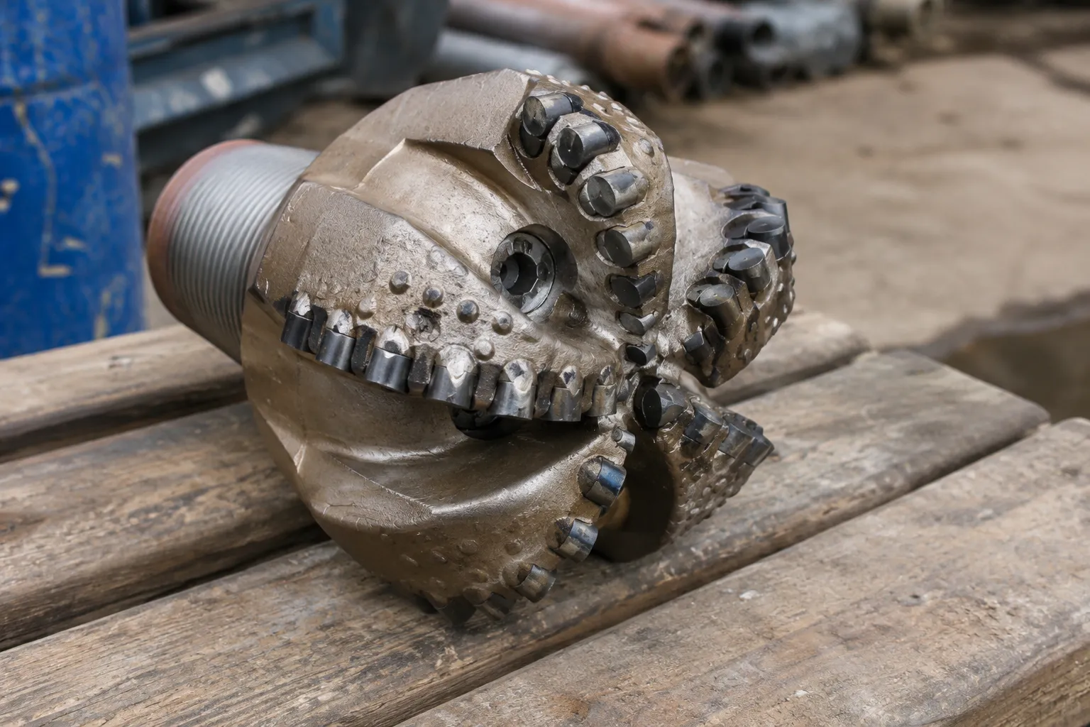
The presence of rock does not automatically mean that a full rock-drilling system is required. However, several conditions may indicate that conventional dirt tooling is unlikely to provide reliable or efficient performance.
Standard drag bits and soft-ground reamers can wear quickly in hard or abrasive formations. Instead of cutting efficiently, unsuitable tooling may scratch the rock surface, generate excessive heat or require increasingly high thrust and torque.
Possible signs that the tooling is being pushed beyond its practical limits include:
Depending on the formation, the project may require tri-cone bits, rock reamers, downhole mud motors or polycrystalline diamond compact tools. PDC tools use extremely hard synthetic diamond cutters and may be effective in suitable formations, although they are not the correct choice for every rock type.
The appropriate tool should be selected using geotechnical information, manufacturer guidance and the contractor’s experience with comparable ground.
Large cobbles, isolated boulders and intensely fractured rock can be difficult to manage with conventional HDD assemblies. A steerable dirt head may ride over an obstruction, move around it or be pushed away from the designed path.
Fractured formations can create additional problems, including:
Purpose-built rock heads, mud motors or other rock-capable systems may provide more concentrated cutting energy and improved control. However, the best approach will depend on whether the project involves continuous competent rock, isolated boulders, broken ground or repeated transitions between materials.
Transitions between soil and rock are among the more challenging conditions encountered during HDD. When a conventional tool reaches an angled or uneven rock surface, it may skate along the formation, deflect sideways or change depth unexpectedly.
Identifying the approximate location and angle of the transition can help the project team:
Mixed-ground bores may require a combination of tooling rather than one system for the entire alignment.
Long crossings beneath roads, rail corridors, waterways or developed urban areas can involve tight tolerances for line and grade. Small deviations in the pilot bore may become significant over a long distance, particularly where hard rock limits the effectiveness of steering corrections.
Rock-rated steering systems or downhole motors may be appropriate where the project requires:
Specialised systems do not guarantee perfect accuracy, but they may provide better control and more consistent cutting performance in formations where standard steerable heads are ineffective.
HDD relies on drilling fluid to cool and lubricate the tooling, carry cuttings from the bore and support the surrounding ground. In heavily fractured rock, limestone with cavities or formations containing open joints, fluid may escape into the surrounding geology.
Loss of returns can reduce cuttings transport and increase the risk of:
The response may involve modified drilling-fluid properties, loss-control materials, reduced pumping pressures, different tooling or changes to the bore design. No single solution is suitable for every formation, so the fluid programme and drilling method should be developed for the identified conditions.
A contractor can make more informed equipment decisions when reliable subsurface information is available before mobilisation.
Useful sources of information may include:
These records may identify rock type, depth, weathering, fracture patterns, groundwater and strength. Where reports show competent bedrock, abrasive material, boulders or long rock intervals, the contractor can assess whether a rock-capable rig and specialised tooling should be planned from the outset.
Visible site conditions can provide useful early warning signs. These may include:
These clues can justify further investigation, but they should not be treated as confirmation of conditions along the entire bore path. Ground conditions may change significantly over short distances, particularly in developed areas with fill, previous excavation and buried infrastructure.
Records from previous HDD installations, utility works and nearby construction projects may help identify recurring subsurface challenges.
References to the following terms can be particularly relevant:
Historical information should still be checked against the current alignment. A nearby bore may have encountered different depths, fills, weathering profiles or groundwater conditions.
Desktop studies and previous reports are valuable, but they do not replace appropriate field verification. Test pits, boreholes and other site-specific investigations can help confirm whether the proposed alignment is likely to encounter the same conditions described in nearby records.
The extent of investigation should reflect the project’s risk, length, depth, installation diameter and proximity to sensitive infrastructure.
A bore path should be designed around the known geology rather than forcing unsuitable curves or depth changes through difficult formations.
Ground information can help the designer and drilling contractor:
In rock, steering corrections may take longer to produce a measurable change in direction than they would in softer ground. Attempting aggressive corrections can increase stress on the tooling and drill string without achieving the desired result.
A gradual bore profile with realistic curve requirements generally gives the drilling team more opportunity to maintain control.
Once the expected rock conditions are understood, the drilling sequence can be planned around the geology.
The pilot tool must be capable of cutting the formation while still providing suitable steering and tracking control. Depending on the ground, this may involve:
A downhole mud motor uses drilling fluid to rotate the cutting bit near the face of the bore. This allows the bit to cut rock without relying entirely on rotation of the complete drill string.
The suitability of a mud motor or other system depends on the rock type, bore geometry, available fluid capacity and required steering performance.

The pilot bore normally needs to be enlarged before product installation. In rock, this may require several staged reaming passes rather than one aggressive increase in diameter.
The reaming plan should consider:
Gradual reaming can reduce tool loading and help maintain circulation, although the ideal sequence will vary from project to project.
Penetration rates in rock can be significantly lower than in soil, but actual performance depends on the formation, tooling, rig capacity and operator technique.
Schedules should account for:
Using verified project information to develop realistic production expectations is more reliable than applying a generic drilling rate to every rock bore.
Rock-capable HDD work often requires a larger or more complex equipment spread than a routine soft-ground installation.
The rig may need additional:
A larger rig is not automatically the correct solution. It must also suit the available footprint, access, bore geometry and installed product.
Rock projects may require several pilot bits, reamers, subs, swivels, drill rods and replacement cutters. These components can be heavier and more difficult to handle than standard dirt tooling.
The site may need enough space for:
Restricted Sydney sites may require detailed staging plans because the rig, tooling and support equipment must operate alongside traffic, buildings, existing utilities and public access routes.
Rock cutting produces abrasive solids that need to be transported out of the bore efficiently. If cuttings accumulate, torque and drag can increase and the drill string may become difficult to move.
The drilling-fluid programme may need to be adjusted to:
Fluid properties should not simply be made thicker without assessment. Excessive viscosity or gel strength can make pumping more difficult and may increase downhole pressure. The programme should reflect the rock type, bore length, annular space, pump capacity and environmental constraints.
Longer or larger-diameter rock bores may also require:
Cuttings and drilling fluids should be managed so they do not enter stormwater systems, waterways or other sensitive areas.
Rock can respond slowly or unevenly to steering inputs. It may also cause vibration, bit deflection or inconsistent progress at changes in formation.
Maintaining bore control may require:
Where the crossing is long, deep or congested, a more advanced guidance system may be needed. The tracking method should be selected for the bore depth, site access, expected interference and required accuracy.
Providing the complete information needed before quoting a directional drilling project helps the contractor assess equipment requirements, site constraints, ground risks and likely project costs.
Equipment selection becomes more reliable when the contractor receives complete project information before drilling begins.
Useful details include:
Where information is incomplete, the contractor may recommend additional investigation or allow for greater uncertainty in the project plan.
The contractor should receive drawings showing:
Tight curves in hard formations can place additional stress on the drill string and installed product. The proposed radius should be suitable for the drilling equipment, tooling and product being installed.
Product details influence the reamed-hole size, number of passes and pullback plan.
Relevant information includes:
Large-diameter or coated products may require careful reaming and fluid control to reduce pullback forces and minimise damage.
Utility locations should be investigated using appropriate records, surface locating and verification methods. As-built drawings alone may not provide sufficient certainty.
The contractor needs to understand:
Congested Sydney corridors may require particularly close coordination because the bore may need to pass beneath roads, rail infrastructure, drainage systems and multiple utility networks.
Project planning should also consider:
These restrictions can affect the choice of rig, tooling, fluid programme and staging method.
Matching the equipment to the formation can improve project reliability and reduce avoidable disruptions.
When unsuitable tooling reaches competent rock, penetration may slow sharply or stop. The crew may need to withdraw the drill string, change the bit or mobilise additional equipment.
Planning suitable rock tooling in advance can reduce:
Rock drilling can still involve uncertainty, but appropriate preparation generally provides a more realistic basis for scheduling.
Rock-rated bits and reamers are designed to maintain their cutting structure and diameter in demanding formations. Selecting an appropriate cutter type can reduce premature wear and help the bore remain closer to the intended size.
Tool life will still vary according to the rock, operating parameters and maintenance. Production estimates should therefore be based on verified conditions and comparable experience rather than broad assumptions about how many metres a bit will achieve.
Specialised rock systems may offer better face control and more consistent penetration than conventional soft-ground tooling.
Improved control can reduce the likelihood of:
No equipment can remove every risk, but selecting a system suited to the formation gives the drilling team a better opportunity to maintain the designed path.
Unexpected rock commonly affects labour, tooling, fuel, fluid use and project duration. Early identification allows these requirements to be considered during pricing and scheduling.
This can reduce disputes over variations and help clients understand why specialised equipment or additional investigation may be justified.
Rock drilling decisions should be made using the best available geotechnical, design and site information. Surface clues and previous project records can help identify potential risks, but they should be supported by appropriate verification wherever the project warrants it.
The final equipment selection should reflect:
Successful HDD projects are more likely when difficult ground is planned for rather than addressed after production has already slowed or stopped.
Daley Directional Drilling combines careful planning, suitable equipment and practical HDD experience to complete challenging installations efficiently and accurately. By assessing the geology, bore requirements and site constraints early, project teams can make informed decisions that protect safety, programme, budget and installation quality.


